


Bell Frames and Bell Towers
A Practical Approach to Assessment
Andrew Dutton
 |
||
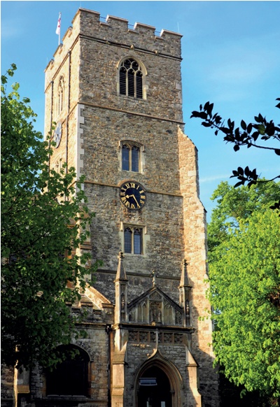
All Saints Church, Fulham, London where the medieval oak bell frame had gradually dried out and warped. The resulting movement had made bell ringing increasingly difficult and was beginning to damage the tower masonry. |
In English bell ringing, or ‘full-circle ringing’, each bell is attached to a wheel on a frame enabling it to be rotated through 360 degrees. Bell ringers regularly need to balance their bell with the mouth upwards, yet the larger, ‘tenor’ bells typically weigh around 500kg. Needless to say, bell ringing is always hard work but any movement in the frame or the tower affects the arc of the swing, making some rings particularly difficult, and bell ringers frequently ask what can be done to make ringing easier.
There are several factors which can affect the quality of the ring. Except for the problem of poor bearings, which can be dealt with by the bell founder, the issues of structural concern are slackness in the bell frames, lack of stiffness in the foundation beams to the bell frames, and movement in the tower itself. These potential movements are caused by the swings of each bell, some of which are oriented north-south and some east-west, so the forces and the subsequent movements are irregular in both time and direction.
The vertical force caused by a swinging bell is close to 4¼ times the deadweight of the bell and the horizontal force can be 2½ times the deadweight of the bell (see Further Information, Heywood). The movements of the bell frame mean that the pivots to the bells are continuously jerking about and that makes it difficult to hold the bell in the upright position, just past top dead centre, on the stay.
Old bell frames were made of timber, braced with diagonal struts and tensioned with iron ties. The timbers flex and the joints ‘work’ during ringing, loosening with time. Regular tightening of the tie bolts can help to minimise the slackness, but the frames are not as stiff as the later cast iron frames and, more recently, fabricated steel frames.
Timber bell frames were usually mounted on timber foundation girders, spanning across the tower but they may have been replaced with steel beams at some stage. The timber bell frame foundation girders are usually of substantial proportion but they will still flex a little and they can also slip in and out of the sockets in the walls. Steel foundation beams are more flexible and need to be substantially braced to limit their flexing. In one church, where a timber frame was mounted in three parallel but unbraced steel beams, the beams were found to be flexing by over 6mm laterally during some ringing sequences. The anchorages of the steel beams in the walls can also be problematic with hammering occurring.
The tower itself can be considered as an elastic structure which will move under the forces induced by bell ringing. Ideally it will act as a single box which is very stiff. However, there are normally weaknesses in the walls of the tower in the form of window and sound louvre openings and it is not uncommon to find vertical cracks running down the centres of each wall from opening to opening. These cracks effectively reduce the stiffness from that of a box with a side of ‘x’ to four angles with a side of half ‘x’, which are therefore much less stiff. In a sense, the action of the bell ringing is trying to reduce the stiffness of the tower to this lower state by increasing the size of the cracks. The natural frequency of the tower will change as the cracks develop.
Cracks can also develop in the window reveals, indicating that the wall thickness is spreading as the rubble fill in the walls is shaken down. This is a particular problem in flint towers.
While the bells are rung to a rhythmic sequence, their different orientation and the ringing changes mean that the imposed forces do not rise and fall smoothly in a simple sine wave, but result in a series of jerks as each bell swings. On occasions this can produce a sequence of pulses which briefly match the natural frequency of the tower.
MONITORING
With careful monitoring, it should be possible to differentiate between the movements of the bell frame, the movements of the foundation beams and the movement of the tower at different levels. This requires measuring movement in each of these three elements simultaneously. From the three sets of data it will be possible to discover what portion of the total movement of the top of the bell frame (and hence the difficulty to ring) is due to slackness in the bell frame, sway in the foundation beams below, and sway in the tower as a whole. The bell ringers can then assess the benefits to be gained from various levels of improvement.
It could easily be the case that a 50 per cent reduction in the movement at the bell pivots can be achieved by improvements to a timber bell frame, whereas the more expensive option of installing new foundation beams might only give a 10 per cent improvement. Similarly, the even more expensive option of lowering the bell frame in the tower to reduce sway itself may give only a very small improvement and, for reasons which will be discussed later, could even result in greater movement.
 |
 |
| This plot shows the movement in the north and south walls of the bell chamber when all bells oriented east-west (the Y axis) are rung simultaneously, producing a large pulse. The effect on the tower is captured by accelerometers attached to the masonry of the north and south walls of the bell chamber. The pulse leads to a jerk on the east-west axis (yellow and green lines) which is much longer than the natural frequency of the tower which is just over 2Hz. | A comparison between the movement of the frame on the north-south (X) axis in red, and the much smaller movement of the south wall (blue) on the same axis. This shows the considerable benefit which can be achieved by stiffening up the frame. |
 |
 |
| This plot shows the movement of the south wall at bell chamber level and the clock chamber 4m below. It can be noted that the impulse momentarily distorts the wall of the bell chamber in the east-west axis (yellow) while the wall below (green) moves much more closely with the natural frequency of the tower. | With a peal (with bells swung in both axes), the frames move much more than the wall in both X (red) and Y (green) axes. The yellow and blue plots give a clear indication of the natural frequency of the tower in each direction. |
Monitoring can take many forms depending on what is being sought. A finger placed across a crack running up the centre of the wall during ringing will be sensitive enough to feel whether the crack is ‘working’ (opening and closing). To determine the benefit of tightening up a timber frame or replacing it with a metal frame, it is possible to install temporary wedging and blocking between the frames and the walls so they cannot move differentially to the tower. This is only a temporary expedient, however, because potential hammering as the wedges loosen can damage the masonry.
Ideally, accurate electronic measurement of all elements simultaneously will yield the most information. Electronic measurement of bell frame movement was developed by the late Harry Windsor of the Central Council of Church Bell Ringers when it became apparent that a lowered bell frame had resulted in increased movement in one church tower. Windsor produced a publication on his method of monitoring and his assessment of why the movement might have increased, based on the harmonics of the bell ringing matching the natural frequency of the tower. He was about to publish a revision to his booklet when he died in 2007 (see Further Information, Windsor).
Windsor’s method of monitoring employed accelerometers mounted on the bell frames and tower with a data logger. The accelerometer information then had to be transferred to spreadsheets for the actual displacement to be calculated by the mathematical process of double integration, a slow and tedious process.
At this time I was developing my own electronic system which automatically calculated displacements from the accelerations and simultaneously carried out the data integration as a continuous process, allowing instant plots of the movement. Three accelerometers, each able to measure the acceleration in the x and y directions simultaneously, could be mounted at key locations. Typical locations are on the bell frame at pivot level, on the foundation beams and on the tower walls in the bell chamber. Another combination may be to locate the accelerometers at different positions up the tower to measure the tower shape as it moves. This, in conjunction with measuring the natural frequency of the tower, will help to predict the benefits of changing the level of the bell frame. Plots A-C (above) show the movement for various combinations of excitation at different locations within the same tower.
 |
|
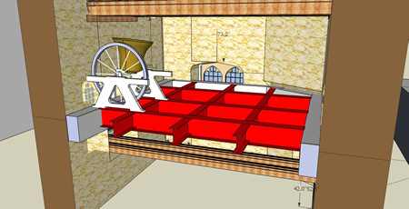
| This typical new bell frame foundation with a concrete ring beam inside the tower walls was installed at All Saints, Fulham (see title illustration). |
When monitoring the movement, there are a number of methods of excitation. To measure the natural frequency of the tower, a single pulse input while measuring the decay frequency would be optimum. It is not possible to achieve that with a full circle swing of a bell due to the complex combination of forces which are applied as the bell swings.
A better method is to have a heavy sandbag swinging on a rope and impacting on a wall. However, in reality, even when ringing a peal, it is possible to pick out the natural frequency from the plots (Plot D).
Determining the maximum potential movement of the tower can be difficult due to the wide range of peal sequences. I have used a combination of the bob minor peal (when bells are rung in sequence) and ‘firing’ (when all the bells are rung simultaneously) in one of the orthogonal directions. Firing will produce a large jerk (see Plots A-C).
Where there are cracks of specific concern, it is possible to measure the movement in each side of the crack simultaneously, with the difference between the two plotlines representing the movement at the crack.
There is a limit to the accuracy of the movement recorded. The electronic integration method introduces background ‘noise’ in the signal. As a result, movements of less than about 0.2mm will be lost in the background noise.
One clear lesson of the monitoring is that human perception is very sensitive and actual movement is usually much less than people expect.
BELL FRAME ALTERATIONS
Stiffening up the bell frame or foundation beams to reduce movement of the tower can have unpredictable effects. The slackness in the system means that the energy transfer from the bells to the tower is delayed, with energy temporarily stored in the frames and beams as they flex, and then released at slightly different times. This can change the frequency of the forces imposed on the tower and it can also increase them.
Imagine placing a football against a wall and kicking it onto the wall. The impact on the foot, and hence the wall will be tolerable. Now replace the ball with a hollow metal ball of the same mass and kick. Broken toes could be the result, indicating a much higher impact force. The energy absorption of the frames and foundation beams is similar. It is possible that stiffening of the frames and foundation beams could increase the movement of the tower, either due to the sharper impact pulse or because the modified input frequency is nearer to the natural frequency of the tower. Unfortunately, monitoring of the tower will not help with this dilemma.
Changing the level of the bell frame can also have unpredictable effects if it means that the force is applied at a position nearer to the point of maximum movement of the tower. Some towers will sway as a simple cantilever from the ground. Others, possibly with stone spires with a higher centre of mass, may develop a ‘standing node’ approximately two thirds of the height, about which the structure oscillates. If the force is applied near the point one third of the height, excitation can occur. Hence the need to monitor the shape of the displacement up the tower. Harry Windsor and others have attempted to analyse what happens but it seems to me that too many changes take place when a bell frame is altered to allow isolation of specific parameters.
Changing the configuration of the bells in the frame can also change the forces on the tower. One of the reasons bell ringers want to have their bell frames modified is to improve the arrangement of the hanging bell ropes. Ideally, they should form a circle so that each ringer can see all the other ringers. This often means changing the direction of swing of some of the heavier bells. The tenor might have been swinging east-west for 200 years and will now swing north-south and be close to the west wall of the tower. The north-south forces in the west wall could increase significantly.
TOWER WEAKNESSES, CRACKS AND REMEDIAL MEASURES
Generally, where vertical cracks have developed in the centre of each wall of a tower, these do not get significantly worse after formation. However, if they do ‘work’ during ringing, tiny particles of debris will work their way down the cracks, slowly enlarging them. Cracks can also be worsened if changes made to a bell frame alter the forces induced in the tower walls. For this reason, when it is proposed to alter a bell frame in a way that will change the forces induced in the tower, it is recommended that the cracks are tied.
Historically, cracks were tied with large diameter iron bars with large pattress plates on the outside to anchor them. The current practice is to use bespoke stainless steel ties such as Cintec. These are drilled through the full breadth of each face of the tower from corner to corner and grouted in place. The core from the facing stone is then re-fixed, leaving an almost invisible repair. The positioning of these ties depends on the configuration of the tower, but generally they are positioned above the openings in the walls at each level.
 |
|
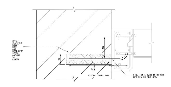
| A typical anchor tie into the wall |
Some towers develop cracks in the window reveals. These are more serious, indicating that the wall thickness is spreading due to the rubble fill in the centre of the wall consolidating and pushing the two masonry faces apart. These cracks are quite common in flint towers where the rounded flints in the centre of the wall can move more easily and wedge down into gaps between the flints below, pushing the faces apart. Spreading is likely to worsen with continued bell ringing.
Through-thickness tying can be used where there are stone or brick facings and the cores can be grouted with a fluid lime mortar grouting. Flint walls can be more problematic due to the difficulty of coring – drilling out the tie holes with a hollow cylindrical bit – and the smaller size of each flint. The Society for the Protection of Ancient Buildings recommends cutting pockets through the wall and building in stainless steel mesh ties (see Further Information), but this may be difficult to achieve in practice.
NEW FOUNDATIONS FOR BELL FRAMES
Occasionally, there is a requirement to install a bell frame in a tower which has not previously had full-swing bells. More commonly, there is a requirement to change the level of a bell frame. In both cases it is first necessary to establish how to install the bell frame while following sound conservation principles.
In the mid-20th century, square concrete rings were often cut into and embedded in the internal faces of the tower with either a concrete floor or integral transverse beams supporting the bell frames. This approach leads to significant loss of original fabric and would be difficult to reverse without causing extensive damage to the original masonry, particularly when breaking out the embedded concrete.
Nevertheless, the concrete ring serves the fundamental function of holding the four sides of the tower together and spreading the forces from the bell ringing more uniformly into the walls. To retain these benefits while minimising loss of fabric, one option is to construct the reinforced concrete ring beam adjacent to the inside face of the tower and tie it to the walls by a series of stainless steel anchor bars grouted into 150mm diameter pockets cored into the walls at regular intervals. If removal were required, the ring beam could be cut using vibrationless methods such as diamond sawing and the anchors in the wall could be cored out.
MONITORING FOLLOWING CHANGES TO THE BELL FRAME
From the viewpoint of the bell ringers, there is nothing to be gained by monitoring after the changes have taken place. However, by improving our understanding of the behaviour of these structures there is much to be learned.
The interaction between full swing bells and bell towers is complex. The forces are significant and all bell towers move. The bell frames on which the bells are mounted distort as the bells swing and they are jerked when an adjacent bell swings. Not only can these forces make ringing difficult, but they can also be highly destructive.
Monitoring can be used to identify where movement is occurring and may demonstrate that there is no need for major changes if the frames can be tightened up. Monitoring can also show the movement shape of the tower and the distortions of the walls. However, monitoring will not be able to determine how the movement of the tower will change for any given alterations to the frames.
With time, if sufficient pre- and post-alteration monitoring is carried out, a better understanding may develop. Harry Windsor was undertaking this work when he died. His work was voluntary, my own is commercial. As a practising structural engineer, I have found bell ringers reluctant to fund work which gives them no direct benefit and I have not been called back to carry out postalteration monitoring. Until we have the opportunity to carry out the ongoing monitoring required, advising on the impact of changing bell frames will remain more an art than a science.
~~~
Further Information
AP Heywood, Bell Towers and Bell Hanging: An Appeal to Architects, Longmans & Co, London, 1914
D Lodge and A Wright, Care and Repair of Flint Walls, SPAB Technical Pamphlet 16, 2000 (see fig 8)
D Robinson and H Windsor, A Practical Analysis of the Interaction Between Church Bells and Towers, The Central Council of Church Bell Ringers, 1994
R Smith and H Hunt, ‘Vibration of Bell Towers Excited by Bell Ringing: a new approach to analysis’, Cambridge University Engineering Department, Cambridge, 2008
H Windsor, Further Analysis of the Interaction between Church Bells and Towers, The Central Council of Church Bell Ringers, 2007