


Timber Roof Structures
and their Asssesment
Ed Morton
 |
||
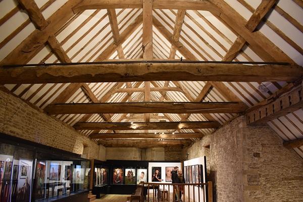
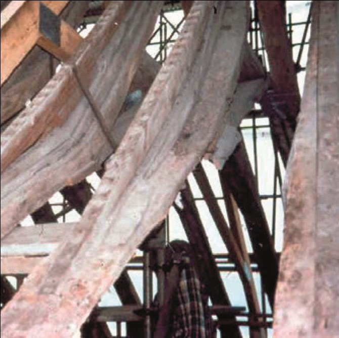
| An example of a purlin roof at Lacock Abbey: in this case the rafters are connected to trusses by two pairs of purlins and the wall plate, while the trusses are tied at eaves level and their midpoint. (Photo: Jonathan Taylor, by kind permission of the National Trust) |
The function of the roof structure is primarily to support roof coverings of slate, tile or thatch, which protect the building from rain, snow and wind. In addition, the space within may provide accommodation for the building, either by the original design or often through later adaptation.
When assessing a roof structure it is important to initially inspect the building both internally and externally to better understand its layout, structural form, the likely phasing of its construction and its general condition. It also provides an initial understanding of any existing health and safety risks which could affect or limit the assessment. In particular, for roof interiors with a floor/ceiling, it must be determined if it is safe to walk over or if the insulation at this level is making this impossible.
It is often helpful to sketch out a plan of the roof to sub-divide it into bays, where appropriate, and produce a cross section marked up with the names of the various members which can then be used in the detailed inspection. This exercise will also highlight major and obvious positions of structural defects such as deflections, bulges or perhaps failures, as well as the most vulnerable areas, principally where water is more likely to become trapped such as gutters, abutments and valleys. While the roof is the target for the detailed inspection, the walls or structure which support it also need to be inspected as they may have been affected by the performance of the roof, or alternatively could have affected the roof through settlement or other defects. This initial inspection will help to determine the scope of the detailed survey.
 |
||
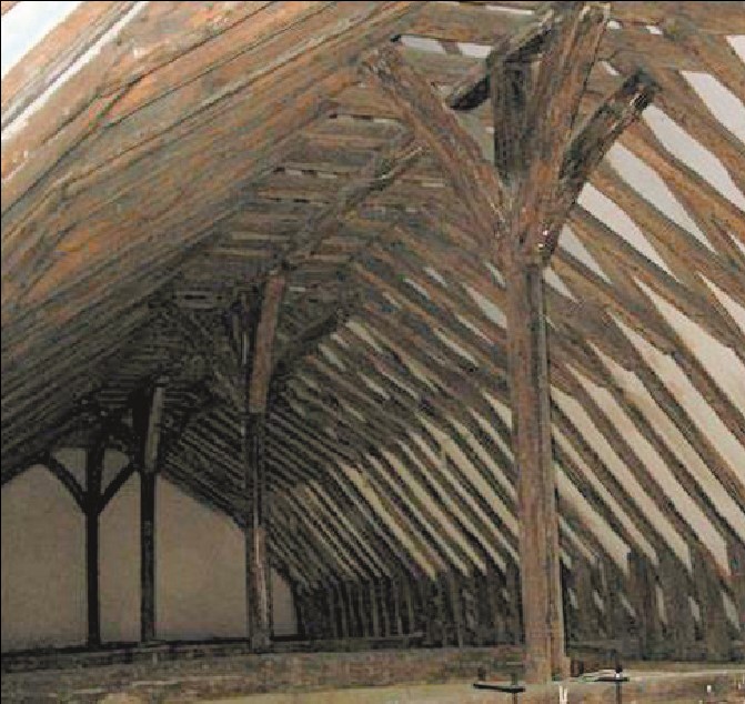
| An example of a rafter roof with crown posts: each pair of rafters is collared at the crown and braced, but there are no purlins. The tie beams provide the main lateral constraint at eaves level and are supported at the midpoint by the crown posts to stop them sagging. (All photos:: Ed Morton, The Morton Partnership unless otherwise stated.) | ||
Moving into the more detailed assessment, firstly it is useful to try and establish how the structure works, by asking questions like ‘how are the loads applied to the roof transferred through to the walls or structure below?’ The roof orientation can be checked in relation to the prevailing weather directions, and the form can be verified by observing if the roof ends in gables, hips, half-hips with gablets or abutments of valleys with adjoining roofs.
Structurally, it is important to understand that pitched roofs generally want to thrust out at eaves level due to the weight applied through roof coverings, finishes and imposed or live loads such as snow and wind. The thrust which is developed must be constrained, with the most efficient form being to introduce ties (of timber or steel) at eaves level across the building. The ties may occur on every rafter or, through the use of trusses, at intervals. However, the architectural design may require a situation with no ties, such as a hammer beam roof truss, or to provide increased height for an attic floor, or for the floor below to have a raised tie or collar.
As a result, historic roofs come in many different forms and styles, and indeed different timber types. Broadly pitched roofs can be sub-divided into two categories: purlin roofs and rafter roofs. In the first, trusses support purlins (horizontal timbers) which in turn support the common rafters. In rafter roofs there are no purlins and it is the common rafters that are the primary structural component, forming a regular pattern of members at relatively close centres. A purlin roof will direct higher loads at the truss bearing points to the structure below, whereas a rafter roof will normally spread the load more evenly across the wall line.
| A pitched roof thrusting out at eaves level. | |
In some cases there may be no need for lateral restraint in the roof structure itself. Sufficient restraint may be provided by thick masonry walls or buttressed walls, or internal structures such as walls and posts may support the roof higher up, significantly reducing the need for restraint. Of course there are historic examples of flat roofs as well, often covered with lead. Although these roof structures can suffer similar problems to pitched roofs, the need for lateral restraint is unlikely.
 |
| An example of ad hoc timbers added over time to help improve the roof. |
Looking in more detail, the roof assessment will need to include checking the rafters for deflections, fractures or splits and areas of decay, either through water ingress or wood boring beetle attack, or a combination of both, or as a result of the use of second-hand timbers which may have been weakened by old mortices or similar. In many medieval roofs the common rafters are laid so that they are wider than they are deep. This is structurally not so efficient and often we find that the rafters have deflected quite significantly. If deflection exists then firring out (or levelling) may have been carried out as part of re-roofing to provide a reasonable plane for fixing battens and applying the coverings. Of course, finishes such as slate have less tolerance for significant undulations as opposed to handmade plain clay peg tiles.
 |
||
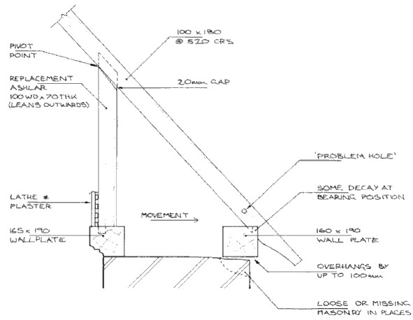
| Eaves detail of a medieval rafter roof with inner and outer wall posts: the foot of the rafter lifted slightly leaving the top of the ashlar post free to move outwards as the roof spread. | ||
Externally, if a roof has reasonably good lines along the ridge and no significant deflections in the plane, but such deformations are found on the inside, one can say with confidence that the roof has not moved significantly since the last re-roofing. Sometimes a roof can appear to be distressed with regular undulations, but this may be undersized or defective roofing battens with the structure itself being sound. So significant movements to the roof or supporting structure may look concerning, but they may not require any repair work if they are at equilibrium and with no progressive movement.
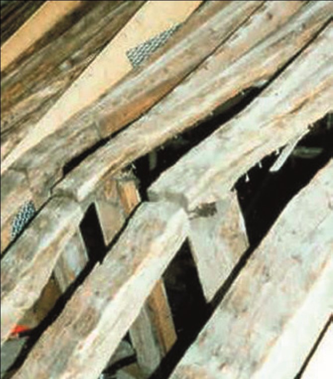 |
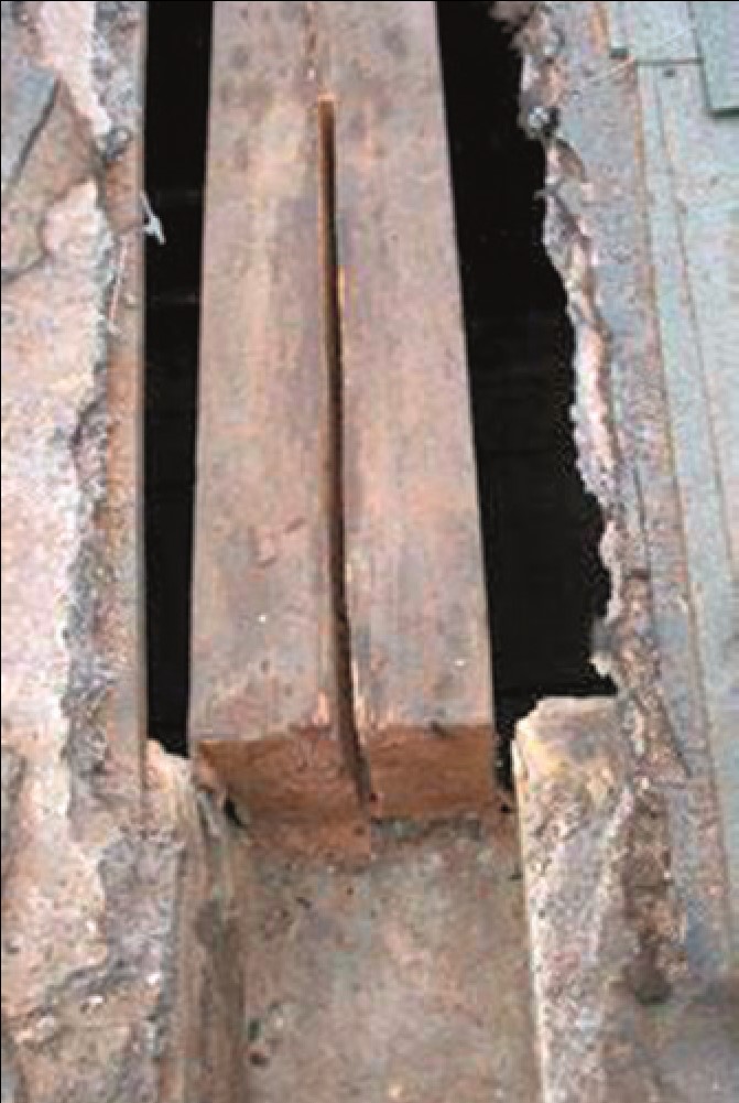
| To accommodate the movement indicated in the diagramabove, these rafters had been cut at the top of the ashlar post, risking collapse. |
As well as the common structure the other principal structural elements need to be checked for defects and deflections, including purlins, trusses and tie beams. Evidence of movement includes opening of joints, failed tenons or pegs. Check for gaps where purlins meet rafters, trusses and gables, and where rafters and trusses meet wall plates. In particular tie beams spanning between opposing eaves plates need to be checked for opening up.
As well as the original structure it is important to try and identify alterations. Purlins can often have struts added from strong points below, or indeed spanning between opposing purlins and cut with a birdsmouth joint. Sometimes truss members and ties are cut to allow better use of the building for accommodation, and elsewhere you may find a rather haphazard arrangement of timbers which have been added at different times.
A common form of medieval roof particularly seen on churches is designed so that the rafters extend down to an outer eaves plate, with an inner eaves plate that supports an ashlar post (a short vertical timber rising to the underside of the rafter) and forms a small triangular void at eaves level secured with tie beams at regular centres. Again there can be variations, such as no wall plates, with each rafter having a stub tie which supports its foot and the post. With the deflection mentioned above occurring in this situation, the posts can become a pivot point, and in extreme cases the foot of the rafter lifts off the eaves plate. A void may open up in the core of the wall, and sometimes the posts can lean back at an angle. Often the repair will look to tie the rafter foot to the inner eaves plate or properly triangulate the joint to help resist this action, with appropriate packing to ensure the plate is supported.
TIMBER DECAY
|
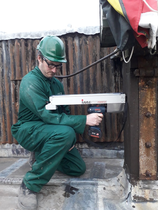 |
| Structural fixings over the existing rafters. | A micro-drill may be used to investigate the condition of timber: variations in the speed at which a 2mm drill bit penetrates timber gives a reliable indication of the depth and extent of decay. (Photo: Hutton + Rostron Environmental Investigations Limited) |
In general terms and pre the mid 18th century, timbers are more likely to be oak, whereas after this date softwood (Scots or Baltic pines) are much more common. However, there are always variations to this including the use of elm, and occasionally black poplar and other local hardwood species. Timber from North America was not imported until the 19th century. Of course the different timbers have different structural characteristics, and varying resilience to decay or beetle attack.
Useful tools for inspecting a timber roof structure include note pads, torches, camera, tape measure, a moisture content reader and a probe to check for concealed decay. This may be a bradawl, penknife or screwdriver. Of course, depending on the significance of the building or the particular elements, specialist equipment for investigations may be warranted. Particularly useful can be a micro-drill which measures and records the density of the timber, thus identifying areas of concealed decay. As it only uses a 2mm drill bit the damage is minimal. A hand drill can also be used in much the same way, but relies on the experience and skill of the user to assess its progress through the timber, to distinguish between sound and decayed areas.
With regard to beetle attack, the general approach is to try and ensure that the moisture content in the timber is kept at low levels (below 15 per cent) in which case beetles will not thrive and the timber will not require treatment.
|
 |
| A rafter foot with a partner timber. | A scarf repair to a tie beam with concealed fixings. |
REPAIRS AND ALTERATIONS
Where structural defects are located and repairs required or where proposed alterations will affect the performance of an existing roof, careful consideration is needed to establish the most appropriate methodology and philosophy for the works. This is influenced by the significance of the fabric affected, the buildability, the cost, and the views of the statutory authority in the case of a listed building.
For a decayed member the two principal options are either to scarf a new section in and joint it appropriately or to apply additional members. These may be in timber or potentially steel. With the former the repair timber may be carefully detailed to work in with the existing, or alternatively the repair may be made obvious, such as a flitch plate repair or the reinforced rafter feet, so it is clear that this is a repair, often termed ‘an honest approach’.
 |
||
| Steel plates to strengthen rafters are placed over the back of the rafters and bolted. | ||
With a deflected rafter, it is possible to improve this by installing structural firrings. These are new timbers, often oak for strength, scribed to the deflected shape and then coach screwed to the top of the existing at close centres. Although this is quite significant alteration work, it improves the structural capability of the rafter considerably. A different option is to install a partner timber alongside and bolt fix through, but this may not be practical where the rafters are exposed. However, if the foot of the rafter is decayed, a short partner timber may well be invisible and uncontroversial.
For a deflected purlin, additional struts can be added from the support structure below, or between opposing purlins, but this may affect how the space is utilised, or not be possible at all. A partner member alongside may be possible, but visually perhaps not appealing, or a steel plate could be run over the back of the rafters and then connected through, creating a diaphragm action.
Where a tie beam or principal rafter end is decayed, it may be possible to cut a slot and insert a steel plate, known as a flitch plate into the member to replace the function of the affected area. Full access and temporary works are likely to be necessary to install this, with bolts set through both the timber and repair plate so they act compositely, with the bolts countersunk and pelleted if required.
|
 |
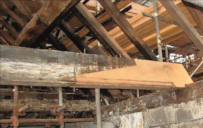
| A steel flitch plate repair to the end of a roof beam | The end of the roof beam with decayed timber cut away, ready for the installation of the flitch plate illustrated on the left. |
Where flitches are not possible, steel plates, channels or angles may be used to fix alongside the defective members. This is perhaps better suited to members which are concealed within floor voids or similar, although where visible the visual impact can be reduced by using specially fabricated steelwork.
In some situations a combined approach of both new timber and steel is required. Care is needed where green oak is used as the tannic acids in the green timber can cause mild steel to corrode, and the use of stainless steel is necessary. This applies equally to fixings with green oak repairs.
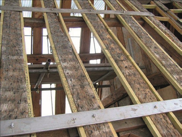
Very occasionally a roof can be found to be in such a condition that more major intervention is required. One example of this was a church medieval roof of rafter form with a double eaves plate where the deflection of the rafters was approximately 300mm (12 inches). Layers of firring timbers had been applied to reduce this effect but the rafter foot must have lifted a considerable distance off the wall plate, to the point where they had been cut over the ashlar post, leaving the main roof in a state of tenuous equilibrium and extremely vulnerable to collapse.
 |
|
| Rafters with 12 inch firring pieces. |
Here an option of inserting new rafter trusses between the existing to support the roof coverings was used, and therefore also the imposed load from wind and snow. The existing structure was retained and the internal finishes (lathe and plaster) applied to this. Although significantly interventionist, it did retain all the historic fabric and was clearly reversible, in that the added truss rafters could be removed at a later date if required.
In conclusion, when assessing historic roofs, ensuring that there is a clear understanding of the significance, the form and geometry, the condition and the defects, is essential. This will allow a clear methodology and philosophy for the works required to be implemented.