


Underfloor Heating
John Minter
 |
|
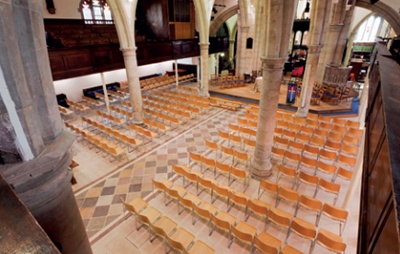
St Mary the Virgin, Ashford, Kent (Grade I listed) following a major re-ordering
programme including a new
limestone floor with underfloor heating installed in
2010/11 using a dry system developed in co-operation with
Jupiter Heating Systems
Ltd (Photo: Robert Greshoff) |
Places of worship come in a wide variety of shapes and sizes and have evolved to suit local needs. Generally, however, they adhere to relatively standard forms of construction, subject to some regional variation, and while the following article is based on the installation of underfloor heating in a typical Anglican parish church, this guidance is generally applicable to other places of worship.
Church heating (where it exists at all) usually comes in two forms. The most common type of system uses cast iron radiators or large pipes, often located against the external walls but less frequently against internal partitions. Pipes (either elderly cast iron or modern ‘finned’ pipes which release heat more efficiently) are also commonly found beneath cast iron grilles which run down the aisles. These are usually fed by gas boilers in a semi-underground chamber. Occasionally this is supplemented by the other widely used system, electric radiant heating coils fixed beneath the pews or on the walls. These are often used as a primary heat source in smaller churches.
Old churches are seldom insulated and often have large expanses of single glazing. Some heat radiates from the appliances but reaches only a small proportion of the floor area, while the rest circulates through convection currents, and most of the benefit is lost as it cools in the upper voids of the building. Much of the perceived warmth tends to come from the body heat of the people in the congregation, who are usually dressed in outdoor clothing.
The 21st-century parish church has often lost its nearby meeting room and in order to best provide for the needs of its community, the church building must be adapted to suit new functions, such as a meeting space, concert or arts venue, as well as providing facilities for youth groups. One option is to replace the pews in all or part of the building with more flexible seating. Although this solution is unthinkable in some fine historic interiors, in many lesser buildings it provides a once-in-a-lifetime chance to resolve a number of building problems in one go.
 |
|
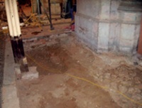
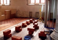
| Excavation to substrate level | |
 |
|
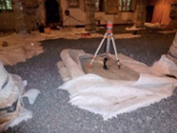
| Foamed glass on geotextile membrane |
Underfloor heating is usually considered in churches where there is a need for an uninterrupted expanse of flooring and a desire to reduce energy consumption. With a low surface temperature of around 29°C, the primary advantage of an underfloor heating system in a church is that heat is provided evenly across a broad area, enabling an ambient temperature of around 18°C to be maintained up to two metres above the floor and emanating from directly beneath the congregation. This means that the visitors readily perceive warmth on entering the building and can shed their coats.
Conventional radiators also have the disadvantage of drawing moisture through the fabric due to the increased evaporation that occurs from the masonry to which the radiator is fixed. If the underfloor heating can be used alone in a particular area, this problem is avoided. However, the time taken for the floor to reach optimum temperature on a cold Sunday morning will never be as rapid as the appliances in a conventional central heating system, so a few radiators are sometimes retained to provide local pockets of warmth while the building warms up.
Considerable fuel savings can be achieved by installing a dual-fuel system where a ground source heat pump (GSHP) can run the underfloor heating, and gas, where available, can heat the radiators. GSHP is a viable source of energy even at sites with sensitive archaeology as it is now possible to extract heat from ground below the archaeological threshold by using radial boreholes, avoiding long trenches for pipes in the churchyard. The possibility of GSHP as a heat source should be considered early on, however, as the water temperature is likely to be lower and the spacing of the underfloor heating pipes needs to be designed with this in mind.
Underfloor heating can also work with solar thermal energy as a source, provided there is space for a large thermal store of warm water, but there are almost always difficulties (ethical and aesthetic rather than practical) associated with installing solar panels on the roof of a historic church.
Insulation can also be installed under the floor at the same time as underfloor heating and, in a historic building, this may be the only place where it can be introduced.
CONSTRUCTION OPTIONS
There are many underfloor heating systems on the market and each needs to be considered with the substrate that goes underneath it and the desired floor finish. The common types of system are described below.
Conventional screed Underfloor heating may be incorporated in a conventional screed, on either suspended beam and block or a solid concrete slab. Properly designed, this provides a firm and level base for a new floor finish and can take high imposed loads. However, generally the heating is slow to respond and the structure as a whole is deep and more expensive to construct, and installation is very permanent. However, the screed provides considerable thermal mass, which means the water flow temperature can be relatively low and during the heating season the heating does not have to be on continually.
Where lime concrete or ‘limecrete’ is used, the system can have the advantage of being breathable and flexible and with pre-heating of the materials it can be installed at any time of year. However, the drying time is lengthy, extending the period the building cannot be used and increasing the contractor’s cost.
Both types of screed also involve putting a large quantity of wet material into a building that may be historically very dry. In historic buildings such a sudden increase in humidity can harm ancient fabric.
Thin screed Underfloor heating can be also be incorporated in a thin (15-25mm) anhydrite screed and stainless steel matrix, laid on the same sort of substrate used for a conventional screed. Because an anhydrite (calcium sulphate) binder is used instead of cement, the overall construction thickness is reduced, requiring less water to be introduced and reducing its drying time. Being thinner, the slab also heats up more quickly, although many pipes are needed as they are smaller than in other systems.
With either screed form it is usually necessary to allow for carefully positioned movement joints and these may be visible in the floor surface.
Insulated tray (dry systems) Some systems use a pre-formed insulated tray with recesses to take the hot water pipes. This system has been widely used with timber flooring, which enables the screed to be omitted. However, one manufacturer has introduced a system of tongue and groove glued terracotta tiles which take the place of the screed and enables stone or clay tiles to be laid on top. This can form part of a completely dry system as described below.
If timber boards are used, it is essential that they are engineered to be suitable for underfloor heating and that a probe is incorporated into the construction that will cut the heat source when the underside of the boards reaches 27 degrees, otherwise the boards will cup and distort.
DRY SYSTEM INSULATION
 |
|
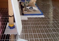
| Insulated heating trays being laid | |
 |
|
| Tongue and groove terracotta tiles being installed |
The layered, dry system which has recently come into use is as follows, starting from the bottom of the excavation:
1. Old pew platforms, terracotta aisle tiles and substrate are removed. Any memorial slabs are carefully recorded and set aside for later reinstatement. The substrate is probed with iron rods to locate any voids (alternatively, if there is time, a ground-penetrating radar survey can be conducted and the results interpreted). The lime concrete ‘crust’ commonly found below pew platforms is then excavated to around 350mm below finished floor level, which is often the depth of the void found beneath the pew platforms. Where sensitive material is found, excavation must be carried out with the utmost care, by hand.
2. Geotextile membrane is then laid on the substrate. The membrane is a woven artificial fabric which separates different types of aggregate material while allowing moisture to pass through. 150mm of recycled foamed glass is then laid and gently compacted. A polythene damp-proof membrane is laid on top, followed by 30mm of crushed slate, which must be carefully levelled.
3. Next, 20mm tongue and groove gypsum boards are laid on the slate, with audiovisual cabling ductwork laid on top of them and the interstices filled with a high-density rigid extruded polystyrene insulation.
4. 30mm expanded polystyrene moulded heating pipe tray with aluminium diffusers and hot water pipes are then installed and overlaid with a separating membrane.
5. Finally, a proprietary system of glued tongue and groove terracotta tiles, 20mm thick, are laid and then overlaid with the chosen floor finish. If desired, an audio induction loop can be laid in the bedding of the floor finish.
ADVANTAGES OF THE DRY SYSTEM
The dry system has many advantages but its success relies on a proper understanding of the site and careful detailing. In a medieval church being adapted in line with typical current patterns of use there will be certain performance criteria which the dry system can usually meet without risk to the floor finish. The key performance criteria for dry systems are set out below.
Loading The new floor should be able to support mobile and stationary loads. Open spaces should enable high-level lighting and redecoration to be carried out from a cherry picker. Generally, a mass of about 500kg per wheel, moving on relatively soft tyres on 25mm temporary plywood sheeting can be safely supported.
Electrical services A new power and audiovisual system is often required as part of the re-ordering. Ductwork and access panels can readily be included in the dry system but detailing is crucial to allow for proper ventilation where required plus considerable capacity for future-proofing and maintenance. Access panels should allow sufficient depth for the long plugs and terminals needed for audiovisual equipment.
The new floor should also be able to incorporate a hearing loop if required. A type of loop known as a ‘phased array’ has been found to work well even though the dry system incorporates aluminium cored pipework and radiant heating plates.
Drainage and ventilation The advantage given by the absence of wet trades should not be negated by lack of control of any groundwater either below the floor or in the churchyard outside, which is often at a higher level than the floor. The new floor will not be fully breathable and so the junction with walls and stone columns must allow for the dissipation of moisture (see diagram overleaf).
All external drainage systems should also be checked, cleared and, where necessary repaired or renewed. Where the ground level is higher than the interior floor level, consideration should also be given to the introduction of French drains – a system of drained trenches which are constructed at the base of the exterior wall to a depth below the interior floor level, and backfilled with a free-draining aggregate. The aim is to reduce the pressure of ground water by ensuring that the perimeter is well drained.
Protecting and recording historic fabric The creation of a new floor will, inevitably mean disturbance of historic fabric but, on completion of the works, this material will at least not be encased in concrete. Depending upon the known history of the church, the implementation of a dry system will mean either a full archaeological investigation or a watching brief following trial pits and a desk study.
The dry system means that the depth of excavation can be kept to an absolute minimum but even with the most detailed research beforehand there are almost always going to be unexpected features below ground, from vaults and early foundations to Victorian gas lighting and heating systems and, of course, human remains.
Features that are to be retained, such as fragile brick vaults with shallow structural arches, are often far enough below the floor system to allow them to be spanned dry with pre-cast concrete lintels but sometimes they are too high and localised concrete caps may be required, all subject to agreement with the county archaeologist and designed by an experienced structural engineer.
The health hazards associated with old burial vaults and ruptured lead coffins must be taken very seriously.
Minimum disruption The nature of the system and the speed of construction means that a re-ordering programme can be carried out with the minimum of disruption to church activities. With the replacement of the floors to nave and aisles in a large parish church, for example, once the church committee volunteers have taken out the pews and loose furniture, the stripping out can commence immediately after the Christmas break and the church can be ready for use by mid June.
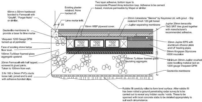 |
|
| Typical new stone floor/existing wall junction detail incorporating perimeter duct for power/audiovisual cabling (Image: Lee-Evans Partnership) |
DISADVANTAGES OF THE DRY SYSTEM
Few disadvantages have been identified with the dry system to date but the primary ones are explored below.
Floor levels To date, the system has relied on being laid to total flatness where large areas are being installed because of the practical difficulties of laying the crushed slate substrate to very shallow falls. Small areas of ramp are perfectly feasible, however. While locally formed ramps can readily be included, a suitable finished floor level must therefore be agreed which addresses adjacent floor levels in the optimum manner. Existing church floors are seldom level and in a large parish church there may be a difference of up to 100mm between one end of the nave and the other.
Future floor fixings Allowance must be made for any future holes in the floor (for doorstops, staff or handrail sockets for example) by putting solid timber blocks in the underfloor heating layers and recording their positions accurately. Although there are specialist tools which can cut the upper layers without disturbing the pipes below, this is not without risk and the consequences of a hole in a pipe would be very serious.
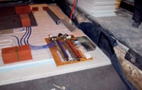 |
|
| Typical manifold installation |
‘Tick-over’ temperature The thermal response time is very rapid compared to other types of underfloor heating but as there is little dense material to provide any kind of thermal mass, the flow temperature of the water should be higher than that required for a conventional screed. During the cooler months the heating system needs to be kept ‘ticking over’ continuously at about 12 degrees so that the heating can quickly be brought up to the desired temperature.
Housing the manifold(s) A home will need to be found for the manifold(s) – the multiple pipe union(s) where single feed and return pipes are divided into several circuits of piped warm water. Manifolds must be located in easily accessible and well-ventilated places.
On balance, dry systems offer perhaps the safest and most practical method of introducing underfloor heating into a church. When combined with the introduction of more comfortable and flexible seating, underfloor heating has obvious attractions for the congregation, and can help to ensure the viability of an underused church. However, not all older churches will be able to benefit from this approach, particularly where their existing flooring, fittings and finishes are deemed too significant to change. The effects of fluctuations in temperature on ancient and fragile fabric also need to be taken into account. Although more easily renewed than a screed, the introduction of a dry system of underfloor heating is not reversible and the loss of any historic fabric always requires careful consideration. In principle and in practice, each case is unique.
~~~
Further Information
British Standard BS EN 12058: 2004, Natural stone products. Slabs for floors and stairs. Requirements, BSI, 2005
British Standard BS EN 1264-5:2008, Water based surface embedded heating and cooling systems. Heating and cooling surfaces embedded in floors, ceilings and walls. Determination of the thermal output, BSI, 2009
Stone Federation Great Britain
Underfloor Heating Manufacturers’ Association